MIDI Ports
- MIDI-In Port allows data to be recieved by a MIDI-compliant device. The In-port is how a MIDI synthesizer is controlled by an external device or sequencer.
- MIDI-Out Port is used for transmitting data.
- MIDI-Thru Port repeats the data that's received by the MIDI-In port; i.e, the incoming dat is retransmitted over the MIDI-Thru port. One's first impression might be that the Thru-port is unnecessary. However, in its original port design, a single MIDI-Out port had limited current and was therefore limited in how many devices it can control.
Fundamental MIDI Configuration

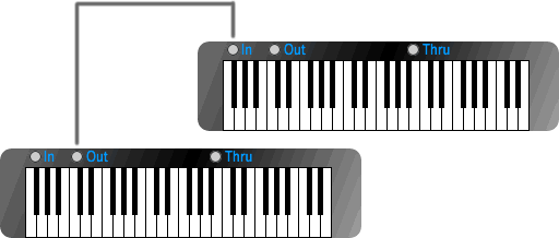
The most fundamental configuration enables the instrumentalist to control a secondary keyboard with the MIDI-Out port from the primary keyboard. In its simplest form, the secondary keyboard plays along with the primary keyboard. This can be used to strengthen the synthesizer's voicing. Additionally, the second keyboard is easily configured to using a different patch along with some effects to improve the overall sound. (Please note that the secondary keyboard could just as easily be a stand-alone syntehsizer that doesn't have an integrated MIDI keyboard. Generally speaking, I like to show both the controllers and synthesizers as keyboards because it's generally recognizable as an electronic device. See my previous article about MIDI Devices if you're unsure about the difference between a controller and a synthesizer.)
A MIDI Pass-thru Configuration

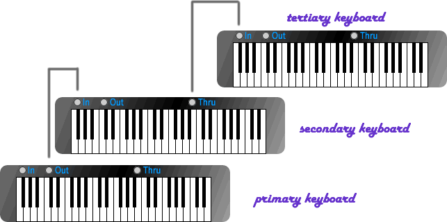
This diagram demonstrates very simply how the MIDI-Thru port can be employed. Again, the musician controls the primary keyboard. The primary-keyboard's MIDI-Out port controls the secondary keyboard. The secondary keyboard is also configured to pass-through incoming commands to the MIDI-Thru port, which controls the tertiary keyboard. Hence, the musician is able to control two additional keyboards via a single MIDI-Out port.
MIDI Messages
Hence, the MIDI-Port is the primary means by which MIDI-sequencers and controllers control a MIDI synthesizer. MIDI ports have physical connections assoicated with them, such as the original 5-pin MIDI connector, however, a MIDI-Port can also be a logical connection. For instance, the Windows Multimedia API is modelled as a MIDI Port. To establish a connection to the local sound card, the programmer needs to open a new MIDI-Out device using the Windiws MM API. Once opened, an application controls the sound card as if it were communicationg over a physical MIDI-Out port. What's common for all types of physical and logical MIDI-Ports is they are used for sending MIDI messages.
MIDI messages are combinations of one or more message or command bytes combined with zero or more data bytes. A byte is an 8-bit unsigned value that can lies between 0 and 255 decimal -- 0 and 0xFF hexadecimal. The most-signification bit of the byte is always 1 for command bytes, while the most-significatn bit is always 0 for data bytes. Hence, command bytes always range between 128 and 255, while data bytes must always lie within the range of 0 to 127. That convention was selected to help MIDI devices readily analyze and interpret MIDI messages bytes as they are recived. One common example of a MIDI message is the note-on command. The following stream of 3-bytes sent over a MIDI-Out port will turn note number 62 on, using channel 0, and with a MIDI-velocity (volume) of 85:
0x80 0x3E 0x55
This byte-string is an example of a MIDI-channel message. MIDI-channel messages are either 1, 2 or 3 bytes in length. Other message types can be much longer than the short-message and are used to support a variety of features. The fundamental types of MIDI messages are shown below:
- Channel Messages are used for controlling one or more of the 16 MIDI channels or for controlling musical notes using a specific MIDI channel. There are only 16 MIDI channels per logical MIDI-Port or connection. In one of my later articles, I'll explain why this absolute maximum number of 16 channels is real drawback when using MIDI for synthesizing just intonation and microtonal music.
- System Exclusive Messages are generally longer MIDI messages that are used for a variety of purposes. One of the primary purposes of the SysEx message is to send manufactuer-specific data to a MIDI synthesizer. Manufactuer-specific data can be used for describing configuration data, sounds samples or timbre, or could provide other specialized command-extensions to a MIDI device.
- System Common Messages some standardized features that are used for controlling the playback of songs in MIDI format and some other miscellaneous features.
- System Real-Time Messages provide some MIDI features for synchronizing the internal timing clocks of connected MIDI devices and for controlling the playback of sequences/songs in MIDI format.
In my next article, I'll add some meat to the bones and provide a detailed description of the available MIDI messages, their binary layouts, and how they are interpreted.
